- #Darlington transistor symbol drivers#
- #Darlington transistor symbol driver#
- #Darlington transistor symbol series#
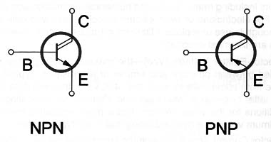
There are two basic types of bipolar transistor construction, PNP and NPN, which basically describes the physical arrangement of the P-type and N-type semiconductor materials from which they are made. The word Transistor is a combination of the two words Transfer Var istor which describes their mode of operation way back in their early days of electronics development.

Transistors are three terminal active devices made from different semiconductor materials that can act as either an insulator or a conductor by the application of a small signal voltage. The fusion of these two diodes produces a three layer, two junction, three terminal device forming the basis of a Bipolar Junction Transistor, or BJT for short.
#Darlington transistor symbol series#
If we join together two individual signal diodes back-to-back, this will give us two PN-junctions connected together in series which would share a common Positve, (P) or Negative, (N) terminal. The bipolar transistor uses one more layer of semiconductor material to produce a device with properties and characteristics of an amplfier. Peak Output Current 2 A Per Channel (1.Unlike semiconductor diodes which are made up from two pieces of semiconductor material to form one simple pn-junction.Output Current 1 A Per Channel (600 mA for L293D).

#Darlington transistor symbol drivers#
Drivers are enabled in pairs, with drivers 1 and 2 enabled by 1,2EN and drivers 3 and 4 enabled by 3,4EN. Both devices are designed to drive inductive loads such as relays, solenoids, DC and bipolar stepping motors, as well as other high current / high voltage loads in positive supply applications.Įach output is a complete totem-pole drive circuit, with a Darlington transistor sink and a pseudo- Darlington source. The L293D is designed to provide bidirectional drive currents of up to 600-mA at voltages from 4.5 V to 36 V. The L293 is designed to provide bidirectional drive currents of up to 1 A at voltages from 4.5 V to 36 V. The L293 and L293D devices are quadruple high current half-H drivers. If your motor matches these specifications, do not hesitate to use L293D.

However, it can withstand a current up to 1200 mA in 100 microsecond and non-repetitive. This IC can set up motors with a voltage between 5V to 36V and a current of up to 600 mA.
#Darlington transistor symbol driver#
There are several reasons which make L293D the preferred driver to the users, such as, cheap price (compared to other drivers), proper shape and size, easy control, no need for protective circuit and diodes, no need for heat sinks and good resistance to temperature and high-speed variations. L293D is one of the most popular drivers in the market. So we need intermediate circuits to connect the controller to the motor, called drivers. But as you know, the output of microcontrollers are 5V and 200mA and can not spin the motor. Therefore, we must control motors using controllers (logic circuits or microcontrollers or PCs or computers). One method is to connect it directly to a battery, then it spins at its maximum speed in a particular direction, but in practice, we need to control the motors (on and off, speed control, direction control, and position control). Depending on the model, the manufacturing method, price, etc., their current is about 100 mA to 5A. Motors used in academic robots normally operate at 5, 6, 9, 12 or 24 volts.


 0 kommentar(er)
